Global Distributors Wanted
1.Free Cloud Service Deployment
2.Free Technical Training
3.Exclusive Territory Protection

1.Free Cloud Service Deployment
2.Free Technical Training
3.Exclusive Territory Protection


Views: 221 Author: Aaron Publish Time: 2026-11-07 Origin: Site


Content Menu
● What Is Crack Detection, and What Can It Tell You?
● How to Choose a Crack Detection Method
● Eight Crack Detection Methods and Their Practical Limits
>> 1. Visual Testing and Drone Imaging
>> 2. Liquid Penetrant Testing
>> 3. Magnetic Particle Testing
>> 4. Ultrasonic Crack Detection
>> 5. Electromagnetic Acoustic Transducer Testing
>> 8. Acoustic Emission Testing
● Drone Crack Detection: Where Automation Helps—and Where It Stops
● A Seven-Step Crack Inspection Workflow
>> 3. Select Complementary Methods
>> 5. Capture Traceable Evidence
● From Low-Altitude Inspection to Underground Coordination
● What a Useful Crack Detection Report Should Include
● Plan an Inspection Around Evidence, Not Equipment
>> 1. Can a drone detect every type of crack?
>> 2. What is the best crack detection method?
>> 3. Can a drone measure crack depth?
>> 4. Is ultrasonic thickness measurement enough to rule out cracks?
>> 5. How reliable is automated crack detection?
>> 6. How often should assets undergo crack inspection?
Crack detection helps asset owners identify damage, prioritize investigation, and make better maintenance decisions. However, reliable drone crack detection requires more than a sharp camera or an automated alert. It requires an inspection method matched to the material, the suspected defect, and the decision the results must support.
For bridges, industrial equipment, tunnels, and other infrastructure, the central question is straightforward: what evidence is needed to determine the next action?
This guide explains the main nondestructive testing methods, where drones add value, and how to build an inspection workflow that connects aerial surveys with qualified technical assessment.
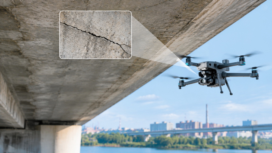
Crack detection is the process of identifying fracture-like discontinuities in a material or structure. Nondestructive testing, commonly called NDT, examines components without intentionally damaging their future usefulness.
Different methods reveal different information. A camera may show a surface opening. Ultrasonic equipment may identify an internal reflector. Magnetic particles may reveal a fine surface discontinuity that ordinary observation misses.
Three tasks should remain distinct:
- Detection establishes whether a relevant indication is present.
- Characterization investigates its location, orientation, dimensions, and nature.
- Engineering assessment determines its significance under applicable service conditions.
An indication is not automatically a confirmed crack. Equally, identifying a crack does not, by itself, establish whether a structure is safe to operate.
The most important principle is verification: match each conclusion to what the inspection actually measured.
Start with the inspection objective rather than the equipment catalogue.
A concrete tunnel lining, an aluminum component, and a carbon-steel weld do not present the same inspection problem. Surface access, coatings, geometry, and expected crack orientation also affect method selection.

| Inspection need | Suitable starting method | Important limitation |
|---|---|---|
| Map visible surface cracking | Visual testing and documented imaging | Cannot establish hidden crack depth |
| Reveal fine surface openings in nonporous materials | Liquid penetrant testing | Requires clean, accessible surfaces |
| Examine ferromagnetic components | Magnetic particle testing | Unsuitable for nonferromagnetic materials |
| Investigate internal discontinuities | Appropriately configured ultrasonic testing | Results depend on technique and coverage |
| Examine conductive surfaces | Eddy current testing | Sensitive to material and probe conditions |
| Screen for thermal anomalies | Infrared thermography | An anomaly does not independently confirm a crack |
This table supports initial planning, not final procedure approval. A qualified NDT specialist should confirm the technique and its suitability for the anticipated damage mechanism.
Visual testing is often the first inspection step. Cameras and optical aids help inspectors document accessible surface conditions and identify areas requiring closer examination.
Drones can extend visual access to elevated façades, bridge components, and industrial structures where a ground-level viewpoint provides insufficient detail.
However, image quality controls what can be detected. Lighting, camera angle, focus, motion blur, and surface contamination can obscure a crack.
A photograph can support surface assessment. It cannot establish that the material beneath an apparently intact surface is defect-free.
Liquid penetrant testing reveals discontinuities open to the surface of clean, nonporous materials.
The process involves applying penetrant, allowing a specified dwell period, removing excess material, and applying developer to make indications visible.
It can help investigate fine surface cracking in suitable metallic and nonmetallic components. However, it does not detect sealed internal defects and is generally unsuitable for porous materials.
Because cleaning and controlled application are essential, penetrant testing often serves as a targeted follow-up rather than a broad aerial screening method.
Magnetic particle testing detects surface and near-surface discontinuities in ferromagnetic materials.
Inspectors magnetize the component and apply fine particles. Discontinuities can produce magnetic leakage fields that attract the particles and form visible indications.
The method is useful for appropriate steel components, but it cannot be applied indiscriminately to aluminum or all stainless steels.
Field direction, surface condition, technique, and interpretation affect results. Qualified personnel must distinguish relevant indications from geometry-related or other nonrelevant patterns.
Ultrasonic testing introduces high-frequency sound into a material and evaluates the resulting signals.
Appropriate techniques can investigate internal discontinuities in welds and other components. Phased array ultrasonic testing and time-of-flight diffraction are among the available approaches for suitable inspection tasks.
A critical distinction matters here: ultrasonic thickness measurement is not automatically a crack examination.
A thickness reading can document remaining wall thickness at a location. Detecting and sizing a crack may require different probes, beam angles, scanning coverage, calibration, and interpretation.
Therefore, a drone carrying a thickness gauge should not be presented as a universal crack-detection system.
Electromagnetic acoustic transducers, or EMATs, generate ultrasonic waves through electromagnetic interaction with a suitable material.
Unlike conventional piezoelectric ultrasonic testing, EMAT techniques do not require liquid couplant. This can offer advantages in selected inspection conditions.
However, material properties, probe spacing, geometry, and the chosen wave mode influence performance.
An EMAT thickness application and an EMAT crack-detection application are not interchangeable. The complete inspection configuration must demonstrate suitability for the intended defect.
Eddy current testing uses electromagnetic induction to investigate conductive materials. Discontinuities can alter the electrical response measured by the probe.
The method can be effective for surface and near-surface inspection, depending on the material and technique.
Probe orientation, frequency, lift-off, coatings, conductivity, and permeability influence sensitivity and interpretation.
Conventional eddy current crack testing should also be distinguished from pulsed eddy current applications used to assess wall loss. A corrosion-screening result does not automatically confirm or exclude a crack.
Infrared thermography maps surface temperature patterns. Under suitable conditions, thermal contrasts can help identify areas requiring further investigation.
It can support broad screening, but the interpretation depends on the asset, heat flow, environment, and inspection technique.
Solar heating, moisture, coatings, and changing weather can all affect thermal patterns. Passive thermal imaging and deliberately stimulated active thermography should not be treated as equivalent.
Use thermal anomalies to guide follow-up inspection rather than assuming every temperature difference represents cracking.
Acoustic emission testing monitors stress-generated signals associated with active processes inside a structure.
It can support investigations involving crack activity under appropriate loading conditions.
However, inactive defects may not generate useful emissions during the monitoring period. Operational noise and other emission sources also complicate interpretation.
Acoustic emission can help locate areas of interest, but additional methods may be necessary to characterize the source and establish its significance.
Drones provide an access and data-collection platform. They do not remove the physical limitations of the sensor they carry.
A practical inspection separates three layers:
1. Access: Can the platform safely reach the inspection position?
2. Evidence: Can the sensor capture information adequate for the task?
3. Decision: Can a qualified reviewer draw the required conclusion?
Automated image analysis can help organize imagery and flag potential defects. Its output should remain reviewable alongside the original images and capture conditions.
A confidence score is not a structural acceptance criterion.
For procurement, ask providers to demonstrate performance against representative defects and surfaces. Attractive demonstration footage does not establish reliable detection across every asset, lighting condition, or crack size.

Specify whether the inspection must locate visible cracking, measure surface width, investigate internal damage, or monitor change.
These objectives require different evidence.
Collect drawings, materials information, previous findings, repairs, and operating conditions.
Use this information to prioritize likely damage locations rather than giving every surface equal attention.
Choose a screening method and define when confirmation is necessary.
For example, aerial imaging may identify a suspect area, while a qualified technician selects an appropriate follow-up examination.
Establish requirements for image sharpness, coverage, location records, and any dimensional measurement.
If crack-width measurement is required, validate the complete imaging and scaling process under representative conditions.
Assign asset and defect identifiers. Preserve original images, inspection dates, viewpoints, and relevant equipment settings.
Make it possible for another reviewer to understand where each finding came from.
Separate confirmed findings from uncertain observations and uninspected areas.
Escalate safety-relevant indications through the asset owner's established engineering process.
Record follow-up testing, engineering decisions, repairs, and reinspection requirements.
An inspection is not complete simply because the flight has ended.
Infrastructure rarely exists in one inspection environment. A facility may include elevated structures, ground-level equipment, and underground spaces.

Shenzhen Intelligent Drone Technology Co. Ltd. (SIDT) describes its approach as integrating dynamic perception, precise data collection, and intelligent analysis across these environments.
Its "one-network coverage" concept centers on a unified intelligent cloud control platform for command, dispatch, and equipment management across multiple nodes.
For crack inspection, the practical opportunity is continuity: connecting screening observations, follow-up assignments, and review records rather than leaving them in separate operational silos.
However, coordinated management does not mean every environment supports the same aircraft or sensor. Underground work requires its own assessment of access, communications, positioning, lighting, and recovery arrangements.
Payload compatibility and any contact-based testing capability should be confirmed for the specific project, not inferred from the platform concept.
A decision-ready report should answer more than "Where did the camera find a line?"
Request the following:
- Asset identification and inspection boundaries.
- Methods used and their limitations.
- Equipment and relevant calibration information.
- Defect locations and original supporting evidence.
- Measurement methods and stated uncertainty where applicable.
- Areas not inspected and reasons for exclusion.
- Reviewer identity and applicable qualifications.
- Recommended confirmation or engineering review.
Use precise language. "No relevant indications detected within the inspected area" is more defensible than "no cracks exist."
For repeat inspections, consistent location references and measurement procedures are essential. Otherwise, apparent growth may reflect a different viewpoint or measurement process rather than actual change.
Reliable crack detection combines suitable access, validated methods, traceable data, and qualified interpretation.
For organizations managing low-altitude, ground, and underground assets, coordinated inspection management can connect those activities into a more useful maintenance workflow.
Contact SIDT with your asset type, material, inspection environment, suspected damage, and reporting requirements. Request a project-specific assessment covering platform suitability, sensor compatibility, validation needs, and specialist NDT involvement before deployment.
No. Camera-equipped drones can document visible surface features when image quality is adequate. Hidden cracks require suitable testing methods. Detection capability depends on the sensor, material, geometry, access, and validated inspection procedure.
There is no universal best method. Visual testing supports surface screening, penetrant testing reveals surface openings, magnetic particle testing examines ferromagnetic materials, and ultrasonic techniques can investigate internal discontinuities. Selection depends on the inspection objective.
Ordinary aerial photographs do not establish crack depth. Depth assessment requires an appropriate measurement technique. Even when a drone carries an NDT sensor, the complete configuration must be validated for that specific task.
No. Thickness measurements describe wall thickness at tested locations. Crack detection may require a different ultrasonic technique, probe arrangement, scan plan, and calibration. A normal thickness reading does not prove the absence of cracking.
Reliability depends on the images, surfaces, defect types, and conditions used to validate the system. Evaluate missed defects and false alerts, not just an overall accuracy figure. Qualified review remains important before maintenance decisions.
Intervals should follow applicable requirements, asset condition, operating exposure, inspection history, and engineering judgment. A newly identified or changing indication may require assessment sooner than the next routine inspection.
1.Original comparison article reviewed for topic coverage and reconstruction. Vendor-specific performance figures and product capabilities have not been transferred to SIDT.
2.Supports the distinctions between inspection methods, material suitability, and surface versus internal discontinuity detection.
3.Supports ultrasonic principles, internal discontinuity examination, and the availability of specialized techniques.
4.Supports penetrant application steps, cleaning requirements, and limitations involving porous materials and subsurface defects.
5.Supports magnetic particle principles and applicability to ferromagnetic materials.
6.Supports the limitations of visual examination and the distinction between directly observed discontinuities and indications produced by other methods.
7.Supports the importance of technician proficiency, procedures, interpretation, acceptance criteria, and reporting.
8. Shenzhen Intelligent Drone Technology Co. Ltd. — company introduction supplied for this article.
Source for SIDT's stated positioning, intelligent flight platform, cross-environment application focus, and "one-network coverage" concept. No public source URL or customer reviews were supplied.


